Thursday, February 24, 2011

Starting Section 21


Now we are talking!
Feel free to enlarge the picture for details. This section covers 20 pages, when I'm finished with it the weather outside will be much warmer!

Section 20 completed


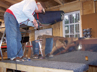
Page 20-04: In case you wonder what this one foot long #30 drill bit is used for, here is the answer. This is step 2 where you have to match drill 4 places on the skin stiffeners: there is no clearance for the drill chuck. I am glad I chose to buy the standard tool kit, in this case it saved me a trip to Lowe's. Note that I had to climb on the table. I guess that I will have to saw its legs as most builders did when they worked on the fuselage.

Visit of Denny Smith's RV-12 in Carthage, NC


I went to see how much Denny's optional interior is covering the floor and sides of the cockpit. I took a few pictures but found out that VAN's web site has much better ones. Anyway I put mine here. Met Denny's plane partner and discussed a few points: priming and painting. They have a nice textured paint for the dashboard so I took a picture of the rattle can they used.

The upholstery gives a very professional look at the interior, you don't have the feeling that you look at an amateur built plane, I believe that it is worth the money.

Denny and his partner have now 6 hours of flight. Clearly the winter weather we had since their first flight in December was not very inviting to take to the air. After my visit I had a sandwich at the Pik'N Pig on the airport and I saw the RV-12 take off with a pretty steep rate of climb.


Tuesday, February 22, 2011

Anne leaving this morning...


Back to Alexandria, but not before squeezing some rivets on the central aft bulkhead assembly she helped me put together.
Tough job but she is a tough Gal anyway!

Monday, February 21, 2011

Starting Fuselage Work in earnest!


It was quite useful to get some help to start this first section of Bulkhead assembly. There are a few questions that pop-up right away because of the complex shape of the bulkhead assembly. They were quickly clarified though by going to the Blogs of my usual (and prefered) suspects John Peck and Marty Santic.


I will comment later

Sunday, February 20, 2011

Nice catch, Anne!


This one was caught by Anne, it is called a flapperon, right flapperon to be exact.
All done in one day, good to get help!
It's now resting with it's brother, the left handed one with the wings in the basement.

Friday, February 18, 2011

One Flapperon Done...

...the left one, one to go, the right one.
The hardest part was the manufacturing of the brackets and drilling of the counterweight. The skins were comparatively easy to set, lots of pulled rivets though relative to the size. The whole job took a full day. It was the first nice day after a long winter, as you can see I was able to
work with the workshop door open, even after dark: nice!

Wednesday, February 16, 2011

Riveting of the Actuator Bracket

This is Page 18-05 step 1

This is a well known challenge because there is not enough clearance for the rivet squeezer's head, even when putting the manufactured head on the side of the leg of the actuator.
For new builders that are just relying on the standard tool kit (mine is from Avery) the question is: is it possible to do the job with the riveting tool provided with the kit (basically 3" hand squeezer and a set of dies including flush sets and one cupped set)?
Answer: yes!
I was able to dot the job by grinding the 1/8" flush set that comes with the tool kit. I also had to put 3 AN960-10 washers ground the same way as the flat set: as the picture on the right shows.


This is the Avery Hand Squeezer equipped for the job: at the bottom the cup set for the manufactured head and at the top the ground Flush set and washers. I did not want to grind the squeezer's head hence the washers.


And a little trick to squeeze the rivets more comfortably:
Put a 2X4 on the leg of the table to block one handle while you push on the other one
(of course it helps to have the handle extender on the Avery squeezer)


... And the job done!


The scuffing of the primer is superficial and cannot be avoided easily in such tight quarters. I will polish the surface and redo some priming tomorrow.

Mulling A-909 counterweight priming

The counterweight is made of stainless steel. It is wrapped around with the Flapperon nose skin as shown in last post pictures. My concern was that the contact between the two different metals: pure AL from the All-clad skin and stainless steel of the tube might be prone to galvanic corrosion. I posted my concerns on VAF at: http://www.vansairforce.com/community/showthread.php?t=68433
The answer is that there is a possibility so I sprayed the counterweights with the NAPA 7220 self etching primer after scuffing them with a scotchbrite pad. I had to unrivet the A1204 ribs which is no problem as the steel tube is hard enough to take several rivet/unrivet cycles (I am at 2 for the right flapperon!). BTW I'm using a rattle can for the NAPA 7220, very convenient for small jobs like this one.

Sunday, February 13, 2011

... And a big mistake is avoided!

I learned two lessons today:
- VAF is a great forum and provides a priceless support through it's members
- Showing what I am doing in my Blog not only helps other builders but also helps me.

To make my story short, Dave Still who is the builder of RV-12 kit 500 after looking at my flapperons picture of yesterday sent me a message telling me that my flapperons looked identical while they should mirror each other. I immediately realized the mistake I had made and went to my workshop to correct it. I also spent a couple hours bringing the right flapperon at the level of the left one, drilling the counterweight. Here is the picture of the two flapperons in the mirror configuration (compare to yesterday picture)
Close call: thank you Dave Still!


Before:


After:


Note to builders: If you make the same mistake, the correction is simple (provided you have not riveted and drilled the counterweight!): just exchange the inboard A 1204 and outboard A 1204 nose rib on one flapperon (in my case it was the right one). This is all it takes to create the mirror configuration.

On the picture the right flapperon is on the left and the left one on the right

Saturday, February 12, 2011

Back to Manufacturing Mode


Fuselage Inventory over, I'm back completing the manufacturing of the Flapperons. I have completed the 2 actuation and 4 pivot brackets, made from aluminum stock - Lots of sawing, filing, grinding, polishing and finally priming with Napa 7220 self etching primer from a rattle can. The pieces are laying on the table, waiting to be riveted on the frames.
I drilled the counterweight of the left flapperon which is a 4 feet stainless steel cylinder 1.5 inch diameter hidden under the skin on the photo. The silver clecos sticking up are going through the skin and counterweight holes. Tomorrow I will drill the right flapperon counterweight which is in the background

Notes for the builders: Drill these holes on a drill press. The steel is too hard for a hand drill and the bit will drift and you will end up with ovale holes in the skin. Just mark the holes through the skin, then remove the tube and put it in a vise on the drill press. For deburring the holes in side the cylinder you attach a round file on a dowel or a broom stick and remove as much as you can inside the tube. It does not need to be perfect as it is steel, it will not crack if not perfectly deburred. Even on the drill press there is a risk of drill bit drifting: you need to mark the hole with a sharp punch before drilling. Also do the drilling first with a #40 bit and finish with the #30, this will create smaller burrs easier to scrap from inside.

The photo on the right shows how I tapped the pivot brackets: put the tap bit in the drill press and turn the chuck by hand. You can see that I secured two pivots brackets at a time in the vise so that I need not make the vertical alignment for each bracket. Vertical alignment for both the tap bit and the hole to be tapped is critical so you need a good Drill Press Vise.

A few helpful links for the builder

These are gleaned from builder's sites but are sometimes buried, I thought it would help to regroup them here:
From Joseph D. Rhodes Builders Log (easier to read and more complete than what's in the book from VANs):
Drill Chart
Tap Chart
Bolt Chart
Rivets Chart
Nut Chart
Washer Chart

Vendors

Tuesday, February 8, 2011

The Fuselage Kit has arrived!

After being delayed one week by the bad weather in the Midwest the fuselage came it today. I had nobody to help as my best friends Randy and René were away but just as we were carying the box I and the driver, my neighbor Richard barged in, warned of the presence of the truck by his dog. The crate is "just" over 200 pounds, not a big deal for 3 guys.
By mid morning the unpacking was well under way:

The fuselage kit is neatly organized into 10 subkits that are wrapped as bundles plus a dozen individual parts, mostly skins and bulkhead frames.
There is also an impressive amount of hardware as the fuselage contains lots of mechanical components and plumbing for gas and hydraulics.

By late afternoon I started making the inventory, starting with the hardware. There are dozens of little bags neatly sorted with bag numbers, however most bags contains several kind of parts and, of course you have to guess which is what as the individual parts like screws, nuts, nutplates and washers are to small to be individually labelled.
I transfered all bag contents into the drawers of a couple of organizers.


Here is where I stand after spending a second day sorting the hardware and labelling the drawers:

A few bags were containg large parts that did not fit in the drawers and ended up in the six bins above the organizers.
For you new builders, this will give you an idea of the amount of drawers you need for the full plane building process. About a half of the drawers were used by the first two kits (empennage and wings)
Some of the drawers have partitions and hold the content of two bags when the bags have few parts.

I plan to spend a few more hours tomorrow inventorying the subkits.

This is the storage occupied by the fuselage kit. There is surprisingly little on the shelves although some subkits are hidden by the tailcone. I think that parts will spread when I unwrap the 10 subkits. All skins are on the top shelf as well as the rear window of the cockpit and are not very visible on the picture.

Tuesday, February 1, 2011

Done with the wings!

(but not yet Gone with the Wind...)
The wings are now out of the way to leave room in the workshop for the fuselage kit which is expected next week.
The storage of the wing is in my basement, by the wine cellar!
(note for the French speaking folks: d'où l'expression "en avoir un coup dans l'aile")


While waiting for the Fuselage, I still have to build the flapperons which are combining flaps and ailerons in the RV-12.